Angled linear gradients in react-native-linear-gradient are broken
February 06, 2022
Table of Contents
How the
linear-gradient()CSS rule works on the webUnderstanding the Chromium code with an example
- Check for undefined slopes
- Center the element on the origin for the calculations
- Find the equation of the gradient line
- Find the corner the gradient will end on
- Find the equation of a line perpendicular to the gradient line that intersects that corner
- Find the point where the gradient line and that perpendicular line intersect
- Go back to the element’s original position
Applying the Chromium solution to
react-native-linear-gradient
Motivation
I’ve been doing some React Native work recently and I’ve been using the plugin react-native-linear-gradient, which promises to provide an easy-to-use component for linear gradients on React Native.
However, I struggled to create a gradient with the proper angle. I tried making a 45 degree angle with their angle props and the angle seemed off:
import React from 'react';
import {SafeAreaView, StyleSheet} from 'react-native';
import LinearGradient from 'react-native-linear-gradient';

const styles = StyleSheet.create({
  container: {
    display: 'flex',
    width: '100%',
    height: '100%',
    justifyContent: 'center',
    alignItems: 'center',
    backgroundColor: '#a0c4ff',
  },
  gradient: {
    width: 320,
    height: 60,
  },
});

const App = () => {
  return (
    <SafeAreaView style={styles.container}>
      <LinearGradient
        useAngle
        angle={45}
        angleCenter={{x: 0.5, y: 0.5}}
        colors={['#FFF', '#000']}
        style={styles.gradient}
      />
    </SafeAreaView>
  );
};

export default App;
The above code renders a black and white gradient. Doesn't appear to be 45 degrees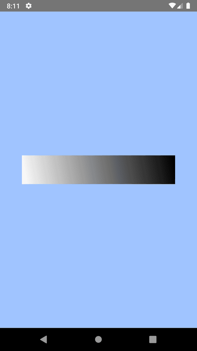
I couldn’t really tell, so I changed the locations prop so that each color takes up 50% to make it more obvious:
const App = () => {
  return (
    <SafeAreaView style={styles.container}>
      <LinearGradient
        useAngle
        angle={45}
        angleCenter={{x: 0.5, y: 0.5}}
        colors={['#FFF', '#000']}
        locations={[0.5, 0.5]} // Add locations, 0.5 = 50%        style={styles.gradient}
      />
    </SafeAreaView>
  );
};
Updated output of the black and white gradient. Clearly not 45 degrees!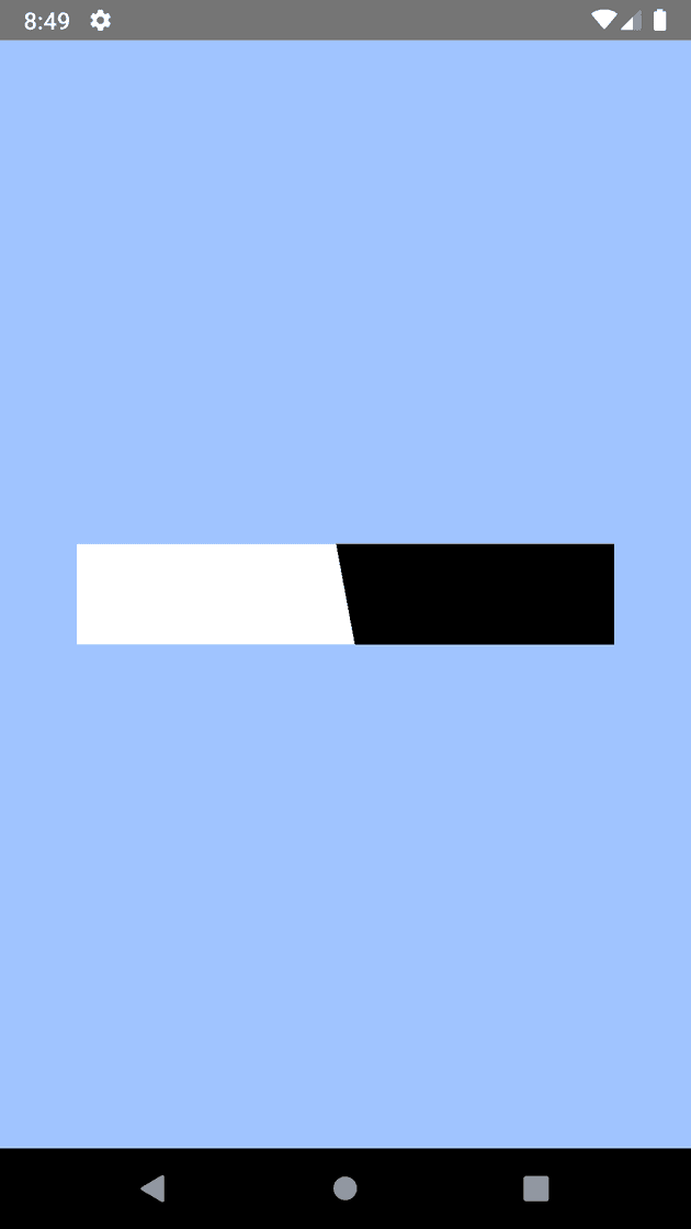
No matter what way you try to look at it, that’s not a 45 degree angle! What’s going on here?
There are a few GitHub issues that have been around for years gone unsolved around these issues:
One commenter even notes:
I also had problems with this. I don’t think the angle property is working on a 360 degree model.
In theory, I could calculate the the start and end points for a given angle properly on my own in JavaScript, but as the documentation for the plugin notes:
One issue is that you have to calculate the angle based on the view’s size, which only happens asynchronously and will cause unwanted flickr.
(Yes, the documentation says “flickr” not “flicker”).
Sounds like I’ll need to figure out what’s going on internally.
How react-native-linear-gradient with an angle works
I took a look at the internals of the plugin. The plugin itself is pretty straightforward and it was easy to locate the relevant code:
    private float[] calculateGradientLocationWithAngle(float angle) {
        float angleRad = (angle - 90.0f) * ((float)Math.PI / 180.0f);
        float length = (float)Math.sqrt(2.0);

        return new float[]{
                (float) Math.cos(angleRad) * length,
                (float) Math.sin(angleRad) * length
        };
    }

    private void drawGradient() {
        // guard against crashes happening while multiple properties are updated
        if (mColors == null || (mLocations != null && mColors.length != mLocations.length))
            return;

        float[] startPos = mStartPos;
        float[] endPos = mEndPos;

        if (mUseAngle && mAngleCenter != null) {
            float[] angleSize = calculateGradientLocationWithAngle(mAngle);
            startPos = new float[]{
                    mAngleCenter[0] - angleSize[0] / 2.0f,
                    mAngleCenter[1] - angleSize[1] / 2.0f
            };
            endPos = new float[]{
                    mAngleCenter[0] + angleSize[0] / 2.0f,
                    mAngleCenter[1] + angleSize[1] / 2.0f
            };
        }

        mShader = new LinearGradient(
                startPos[0] * mSize[0],
                startPos[1] * mSize[1],
                endPos[0] * mSize[0],
                endPos[1] * mSize[1],
            mColors,
            mLocations,
            Shader.TileMode.CLAMP);
        mPaint.setShader(mShader);
        invalidate();
    }
Time to brush up on my trigonometry and geometry. Starting with this first line:
float angleRad = (angle - 90.0f) * ((float)Math.PI / 180.0f);The goal of this line is to convert degrees to radians. To convert, consider that and apply the proportion and solve for angleRad.
But where does the (angle - 90.0f) come from? Maybe it’s an attempt to convert from cartesian coordinates to a “bearing angle” like you’d find on a compass, where 0° is North and 90° is.. wait, by this math, it would be West? That doesn’t seem right then. East should be 90°. Maybe it’s for another reason? In the drawing space (as the code I reference later refers to it), the Y coordinates are positive below the X axis. That could be related, though I don’t think a simple rotation would correct that? Perhaps the math later explains it.
Moving to the next lines:
        float length = (float)Math.sqrt(2.0);

        return new float[]{
                (float) Math.cos(angleRad) * length,
                (float) Math.sin(angleRad) * length
        };
The return value here is a vector representing the original angle with X and Y components. From trigonometry, is the X component of whereas is the Y component, such that the unit vector of is .
A trig review of how this works: To get a unit vector of , make length of c, or . Solve for X and Y.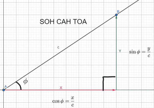
However, they multiply the unit vector by length so that it has a magnitude of . Why? Maybe the later math will make it make sense?
Inside the drawGradient function is this:
        if (mUseAngle && mAngleCenter != null) {
            float[] angleSize = calculateGradientLocationWithAngle(mAngle);
            startPos = new float[]{
                    mAngleCenter[0] - angleSize[0] / 2.0f,
                    mAngleCenter[1] - angleSize[1] / 2.0f
            };
            endPos = new float[]{
                    mAngleCenter[0] + angleSize[0] / 2.0f,
                    mAngleCenter[1] + angleSize[1] / 2.0f
            };
        }
I’ll use mAngleCenter = [0.5, 0.5] since that’s what it is in my example code. I don’t see any use case for an angle center that’s not the center of the element anyway.
I’ll start substituting in the math so it’s easier to keep track:
Because the props are all given as relative values based on width and height, before they pass the values into the shader they multiply the relative width and height values to get the real values:
        mShader = new LinearGradient(
                startPos[0] * mSize[0], // start X
                startPos[1] * mSize[1], // start Y
                endPos[0] * mSize[0], // end X
                endPos[1] * mSize[1], // end Y
            mColors,
            mLocations,
            Shader.TileMode.CLAMP);
Thus, my equations become (with = width, = height):
Let me see what happens when I use a 135° angle. I remember I have to subtract 90° to when getting the radians, so it’s a 45° angle in these calculations. , so subbing that in:
, so simplifying that further:
Hm. The final result? The start position is and the end position is
It’s like they assume the element is square - going from to isn’t necessarily 135°!
Going from to (ignore the negative in the illustration, positive Y direction is down in draw space) does not create a 135° angle.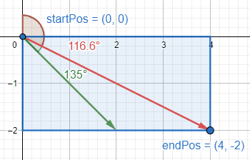
From which quadrant it landed in, it looks like they’re going for a conversion from “bearing angle” to cartesian, much like I mentioned before, but used an extra bit of trickery with the signs on the last step to correctly flip it around.
This brings up the question: What should the math look like?
How to apply a rotation transformation to a point
I set out to do my own solution, hopefully changing as little of the code as possible. After I saw they had the correct angle as mAngle, and the correct X and Y multipliers as cos(angleRad) and sin(angleRad) respectfully (although multiplied by ), I realized the problem must be elsewhere, which is how I noticed at the very last step they multiply the X component of the vector by the width, but the Y component by the height. This creates a skew as the magnitude of the component vectors no longer match the ratio set by the unit vector of
What if I instead multiply both the X component and the Y component by the half the width? Or half the height? Or whichever is larger? That way they both scale equally, so the angle should be preserved.
I have three requirements:
- The gradient must start before the area which will render
- The gradient must end after the area which will render
- The gradient must have the angle specified
Note that the solution in react-native-linear-gradient only satisfies the first two requirements.
For my solution, I applied the simplest case - a straight, horizontal gradient - and rotated it. I had the gradient start at and end at , and then rotated around .
However, if I simply rotate based on the midpoint, I fail at requirements #1 and #2. Note how in the figure below, the gradient will start too late and miss the top left corner of the rectangle (visualized by the red line).
Simply using as the initial point and rotating it around the center of the element won't work. The new 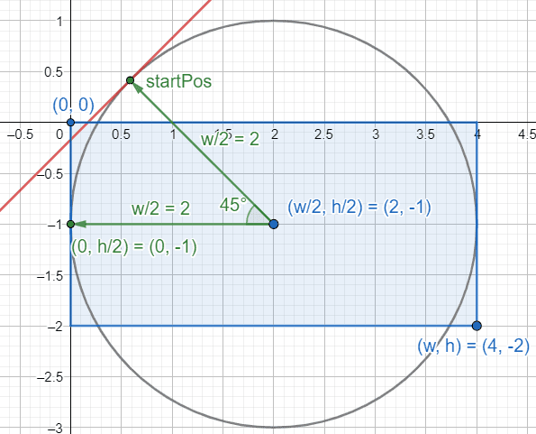
startPos isn't far enough away.
I thought maybe I could use the distance to the corner as the radius, but I’d need to take into account the original angle of the corner and my startPos would get too far away. That wasn’t a requirement, but it needs to be since otherwise the gradient might not fully transition to the proper color within the element!
Even if that would have worked, it’s worth noting that the calculation gets more expensive: I’d have to either calculate the distance from the center to the corner or calculate the angle from the center to the corner, introducing either another sqrt() or tan().
Look at how far 
startPos gets from the render area if I use the distance to the corner as the radius.
The distance became much more apparent when comparing the solution for React Native vs the linear-gradient() on web. The same gradient looked way different. Since the gradient has to cover a much larger space, my solution introduced subtle banding issues. The start and end of the gradient were too far away from the rendered element and their true colors weren’t seen at all in the gradient.
I modified my requirements:
- The gradient must start exactly at the start of the area which will render
- The gradient must end exactly at the end of the area that will render
- The gradient must have the angle specified
Interestingly, it appears from my example that react-native-linear-gradient may still satisfy the first two requirements, though that may not be the case and I didn’t bother proving it.
Maybe it’s time to see how linear-gradient() on the web works.
How the linear-gradient() CSS rule works on the web
MDN describes linear gradients extremely well:
A linear gradient is defined by an axis—the gradient line—and two or more color-stop points. Each point on the axis is a distinct color; to create a smooth gradient, the linear-gradient() function draws a series of colored lines perpendicular to the gradient line, each one matching the color of the point where it intersects the gradient line.
In summary, linear gradient has colors, color stop points, and a start and ending points. What I’m concerned with is those start and end points. Additionally, the linear gradient can be thought of as a series of colored lines that run perpendicular to a “gradient line.”
The picture below that paragraph tells a thousand words:
MDN image explaining the gradient line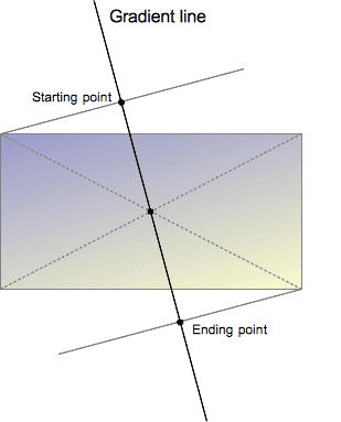
Note that the gradient starts at the point in which a line perpendicular to the gradient line would first intersect the element. In other words, the gradient starts flush with the element. The same goes for the end. That’s what I need to mimic. That’s how I satisfy the first two requirements. The question, then, is how to preserve the angle.
I also gain clarity about angle in the linear-gradient(). MDN settles it:
The gradient line’s angle of direction. A value of 0deg is equivalent to to top; increasing values rotate clockwise from there.
Awesome. Man, I love MDN… if only I checked it first before looking at Chromium’s source code I could have derived the solution myself, which would have been fun.
How Chromium does it
Here’s the Chromium source for how they calculate gradient start and end points:
// Compute the endpoints so that a gradient of the given angle covers a box of
// the given size.
static void EndPointsFromAngle(float angle_deg,
                               const gfx::SizeF& size,
                               gfx::PointF& first_point,
                               gfx::PointF& second_point,
                               CSSGradientType type) {
  // Prefixed gradients use "polar coordinate" angles, rather than "bearing"
  // angles.
  if (type == kCSSPrefixedLinearGradient)
    angle_deg = 90 - angle_deg;

  angle_deg = fmodf(angle_deg, 360);
  if (angle_deg < 0)
    angle_deg += 360;

  if (!angle_deg) {
    first_point.SetPoint(0, size.height());
    second_point.SetPoint(0, 0);
    return;
  }

  if (angle_deg == 90) {
    first_point.SetPoint(0, 0);
    second_point.SetPoint(size.width(), 0);
    return;
  }

  if (angle_deg == 180) {
    first_point.SetPoint(0, 0);
    second_point.SetPoint(0, size.height());
    return;
  }

  if (angle_deg == 270) {
    first_point.SetPoint(size.width(), 0);
    second_point.SetPoint(0, 0);
    return;
  }

  // angleDeg is a "bearing angle" (0deg = N, 90deg = E),
  // but tan expects 0deg = E, 90deg = N.
  float slope = tan(Deg2rad(90 - angle_deg));

  // We find the endpoint by computing the intersection of the line formed by
  // the slope, and a line perpendicular to it that intersects the corner.
  float perpendicular_slope = -1 / slope;

  // Compute start corner relative to center, in Cartesian space (+y = up).
  float half_height = size.height() / 2;
  float half_width = size.width() / 2;
  gfx::PointF end_corner;
  if (angle_deg < 90)
    end_corner.SetPoint(half_width, half_height);
  else if (angle_deg < 180)
    end_corner.SetPoint(half_width, -half_height);
  else if (angle_deg < 270)
    end_corner.SetPoint(-half_width, -half_height);
  else
    end_corner.SetPoint(-half_width, half_height);

  // Compute c (of y = mx + c) using the corner point.
  float c = end_corner.y() - perpendicular_slope * end_corner.x();
  float end_x = c / (slope - perpendicular_slope);
  float end_y = perpendicular_slope * end_x + c;

  // We computed the end point, so set the second point, taking into account the
  // moved origin and the fact that we're in drawing space (+y = down).
  second_point.SetPoint(half_width + end_x, half_height - end_y);
  // Reflect around the center for the start point.
  first_point.SetPoint(half_width - end_x, half_height + end_y);
}
Look at those wonderful comments left by the dev. I don’t have to guess at what’s happening here.
Here’s what they do (and what I need to do) - don’t worry, I’ll add pictures to explain in more detail later:
- Handle all cases where a denominator in the calculations could be 0.
- Translate the element such that it’s centered on the origin (also convert to cartesian coordinates).
- Find the equation of the gradient line using slope of the angle and as the Y-intercept.
- Figure out which corner of the element the gradient ends at.
- Find the equation of a line perpendicular to the gradient line that intersects that corner.
- Find the intersection point of that perpendicular line with the gradient line. This is the gradient’s end point.
- Translate the end point from the origin back to the center of the original element, undoing step #2 (also convert back from cartesian). Reflect the end point over the center of the element to get the start point.
Understanding the Chromium code with an example
I used the Chromium method on some values to see how it works alongside some visuals. Here are the givens I’m working with:
I have an element whose dimensions are width $ w = 4 $ and height $ h = 2 $
The angle for the gradient is , in “bearing” degrees, meaning North is 0°, East is 90°, etc (not that it matters for 45°, as its the same in both).
Check for undefined slopes
First thing to do is check for the desired angle being vertical or horizontal. This is required since I’ll be working with slopes and the slope of vertical lines is undefined. Since I’m dealing with perpendicular lines to that angle, also check for horizontal slopes.
This is the Chromium code matching this step:
  angle_deg = fmodf(angle_deg, 360);
  if (angle_deg < 0)
    angle_deg += 360;

  if (!angle_deg) {
    first_point.SetPoint(0, size.height());
    second_point.SetPoint(0, 0);
    return;
  }

  if (angle_deg == 90) {
    first_point.SetPoint(0, 0);
    second_point.SetPoint(size.width(), 0);
    return;
  }

  if (angle_deg == 180) {
    first_point.SetPoint(0, 0);
    second_point.SetPoint(0, size.height());
    return;
  }

  if (angle_deg == 270) {
    first_point.SetPoint(size.width(), 0);
    second_point.SetPoint(0, 0);
    return;
  }
Since the given 45° angle isn’t a multiple of 90°, there’s no action needed for this example. Move to the next step.
Center the element on the origin for the calculations
Next, translate the element. This way I can have all the math be a bit more simplified. Without it, I’d need to find the Y intercept of the gradient line and use that in the equation for the intersection. I’ll just move it so that I don’t need to do that and then I can simply move my solution back at the end.
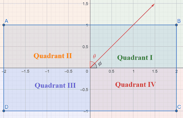
Here I graphed the original element and the translation. The blue rectangle is the original location (converted from the drawing space to cartesian) and the green is the newly translated rectangle. (Chromium’s code also converts to cartesian (positive Y = up) at this step, and uses cartesian up until the final step).
Translate the element such that it's centered on (0, 0).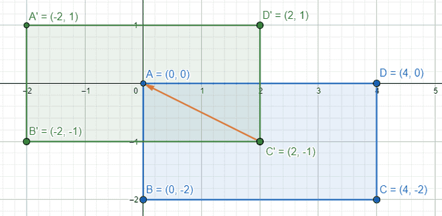
There’s no code for this step, it’s just a mental step to frame the rest of the calculations.
Find the equation of the gradient line
The equation for the “gradient line” is derived using the angle. The angle is given as a “bearing angle” (meaning it has North = 0°, East = 90°, etc) so convert it to cartesian. In “bearing angles,” East is 90°, but in cartesian, East is 0°, so first subtract 90°. Like MDN noted above, “bearing angles” increase clockwise, but in cartesian, angles increase counter-clockwise, so invert it as well to change the positive direction. I’ll call this new angle :
Now that the angle is in cartesian, I can use trigonometry to get the equivalent slope for a line of that angle. The slope of any line is defined as “rise over run.” In other words, slope is the distance moved in the Y direction divided by the distance moved in the X direction when comparing two points: . From SOH-CAH-TOA, is equal to the “opposite” over the “adjacent.” I can draw a right triangle on the origin with the angle like so:
A right triangle with as the angle for the vertex at the origin
With that right triangle, to get the slope of , I can use B and A’s coordinates and plug them into the slope equation:
Note that the length of the side opposite is , and the length of the side adjacent to is , such that:
Thus the slope of the line representing an angle is found using . Substitute in and the equation to find becomes:
where is the slope of the gradient line.
The calculation for matches the code:
  // angleDeg is a "bearing angle" (0deg = N, 90deg = E),
  // but tan expects 0deg = E, 90deg = N.
  float slope = tan(Deg2rad(90 - angle_deg));
Note that since the “stripe” lines of the gradient extend in both directions infinitely, it doesn’t really matter where the Y-intercept of this line is, just what the slope is. If I wanted, I could pick a Y-intercept of 1000, and do all the calculations from there. However, using the origin allows the simplicity of reflecting the end point across the center of the element by just flipping signs to get the start point in step 7. So I’ll stick to using that.
A line is defined as a function of the independent variable that calculates in the form:
The Y intercept for the gradient line is 0, as noted above. So the equation for the gradient line is:
This equation isn’t in the code until it’s used in a later calculation.
With the 45° angle provided for this example, the slope of the gradient line is 1:
Thus the equation for the gradient line for this example is:
Find the corner the gradient will end on
Chugging right along, next up is to figure out which corner is the one that will mark the end of the gradient.
Here’s the thinking behind this: The gradient I’m drawing is a linear gradient which means I can think about the gradient in “stripes” of solid color lines. In the case of a horizontal gradient, this would mean vertical “stripes.” Note that the “stripes” are perpendicular to the gradient line. If I angle the gradient line, the “stripe” lines are also angled.
I want the last “stripe” of the gradient to be perfectly flush with the element. I don’t want the last “stripe” to be past the element’s render area nor for it to be inside the element’s render area. As I saw above in my naive solution, that would cause problems as the end color either gets reached too late or too soon. In other words, I want the final “stripe” to intersect the element at a single point.
In step #1 I’ve already ruled out vertical and horizontal gradient lines, and the element is defined as a rectangle, so there’s no chance for the line to be parallel with any of the rectangle’s edges. Therefore, if this “stripe” line intersects at two points, that means it’s inside the element (ends too soon), and if it doesn’t intersect, that means it’s outside the element (ends too late). The only place a line can intersect exactly once is on a vertex, therefore my final “stripe” line must intersect at a corner of the element rectangle.
Visualization of "stripes" and how the final "stripe" intersects a corner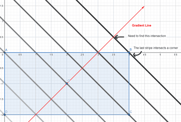
In the code and in my analysis, this final “stripe” line is the “perpendicular line.”
Determining which corner the perpendicular line will interesect is like playing “spin the bottle.” Draw the gradient line from the previous step starting at the origin. The corner that is closest to where that line lands on the translated element is the corner that the perpendicular line will intersect.
Another way to think about it is based on the quadrant of the given angle. The corner of the translated element and the angle share the same quadrant. Recall that the quadrants in cartesian systems go counter clockwise starting from the top right, but also that the angle is given in “bearing” degrees.
- If the bearing angle is between 0 and 90°, it’s in quadrant I, so choose the top right corner.
- If the bearing angle is between 90° and 180°, it’s in quadrant IV, so choose the bottom right corner.
- If the bearing angle is between 180° and 270°, it’s in quadrant III, so choose the bottom left corner.
- If the bearing angle it’s more than 270° it’s in quadrant II, so choose the top left corner.
The corners after translating the element to be centered at the origin are:
- Top right:
- Bottom right:
- Bottom left:
- Top left:
This matches the code (angle_deg here is still a “bearing” angle):
  // Compute start corner relative to center, in Cartesian space (+y = up).
  float half_height = size.height() / 2;
  float half_width = size.width() / 2;
  gfx::PointF end_corner;
  if (angle_deg < 90)
    end_corner.SetPoint(half_width, half_height);
  else if (angle_deg < 180)
    end_corner.SetPoint(half_width, -half_height);
  else if (angle_deg < 270)
    end_corner.SetPoint(-half_width, -half_height);
  else
    end_corner.SetPoint(-half_width, half_height);
For the given angle of 45° in the example, the corner to be intersected is determined to be the top right, or for the translated rectangle in cartesian coordinates.
Plugging in the given height and width for the example:
Find the equation of a line perpendicular to the gradient line that intersects that corner
Time for the next step: to find the equation of the perpendicular line. The slope is easy enough. It’s perpendicular to the gradient line, so its slope is the inverse of the reciprocal of . Letting the slope of the perpendicular line be :
The slightly harder part is finding the y-intercept. Using the corner selected in step 3, however, I can calculate it simply by plugging in to the line equation (I’m using instead of to stay consistent with the Chromium code):
Rearrange to solve for c:
The calculations for and match the code:
  // We find the endpoint by computing the intersection of the line formed by
  // the slope, and a line perpendicular to it that intersects the corner.
  float perpendicular_slope = -1 / slope;
// Compute c (of y = mx + c) using the corner point.
float c = end_corner.y() - perpendicular_slope * end_corner.x();Now to get the solutions for the example provided. From a previous step, I got the equation for the gradient line and , so the slope of the perpendicular is:
Plug in the corner point from the previous step of and the solved to find the Y intercept:
Thus the equation for the perpendicular line is:
Now that I have the equations for both lines, I can calculate the intersection in the next step.
Find the point where the gradient line and that perpendicular line intersect
Now to find the end position solve for the intersection of the perpendicular line and the gradient line. That intersection will be the gradient’s end point, as it marks where the gradient has to go such that it will end on the corner but still retain the proper angle.
From previous steps, I know that the equation of the gradient line is:
and the equation for the perpendicular line is:
So to solve for , I can simply do:
Subtract from both sides:
Distributive rule:
Divide both sides by
This solution for the endpoint X coordinate matches the code:
float end_x = c / (slope - perpendicular_slope);Plug the found X value for the intersection into the equation for the perpendicular line to find the Y value (also would work to use the equation for the gradient line):
which matches the code:
float end_y = perpendicular_slope * end_x + c;Now plug in the values gathered in previous steps to get the solution for the example. From previous steps, , , and . So plugging those into the equation:
And then plugging that solution for into the equation for the perpendicular line to find :
Thus the pre-translation end point for the gradient is or
The below figure shows a visual of the calculations so far. The green line is the “gradient line”. The thick red line is the perpendicular line. (Note: We didn’t calculate the start point yet, but note that it’s simply the end position reflected across the origin!)
The calculations done for the example, graphed out visually.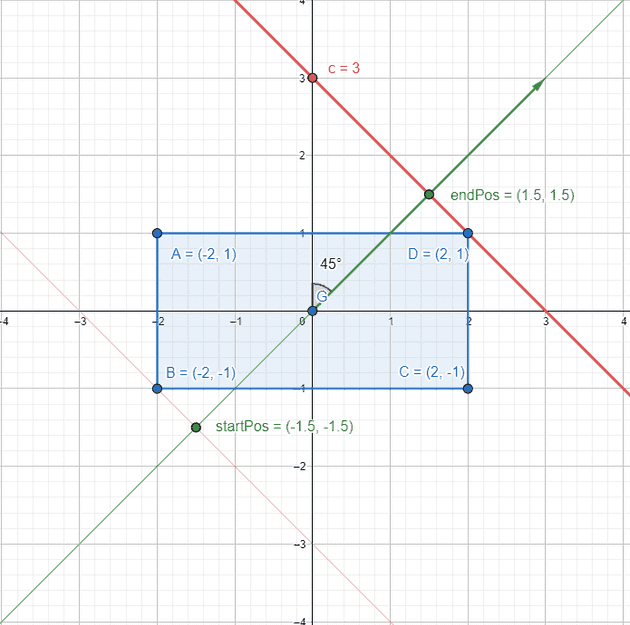
Go back to the element’s original position
Translating the points back to the original element means adding back what I subtracted in the second step. I also have to keep in mind that the Y axis is positive down in the drawing space, so I invert the Y coordinate of the endpoint to convert it from cartesian back to the drawing space at the same time:
Then, flip the operations to get the start position by reflecting the end point across the center of the element:
This matches the code:
  // We computed the end point, so set the second point, taking into account the
  // moved origin and the fact that we're in drawing space (+y = down).
  second_point.SetPoint(half_width + end_x, half_height - end_y);
  // Reflect around the center for the start point.
  first_point.SetPoint(half_width - end_x, half_height + end_y);
Now to plug in the example values, remember that , , and :
The final end position for the gradient is
The final start position for the gradient is
The final solution for the start and end positions (in cartesian coordinates)
Applying the Chromium solution to react-native-linear-gradient
It seems like react-native-linear-gradient should mirror what the web does. The general flow for designers is to create in an app like Figma which will give developers the web version of a gradient anyway. It doesn’t make sense for devs to have to “guess and check” what angle matches the web version.
I created a pull request on the react-native-linear-gradient repo which has gotten merged, so this problem should be fixed by the next major release. For now, if you want to use it, reference the master commit in your package.json like so:
{
  "react-native-linear-gradient": "github:react-native-linear-gradient/react-native-linear-gradient#9aece37cdf7d33ed52a1747b36e9e84f3c7a49ef"
}
And that’s it!
      <LinearGradient
        useAngle
        angle={45}
        angleCenter={{x: 0.5, y: 0.5}}
        colors={['#FFF', '#000']}
        locations={[0.5, 0.5]}
        style={styles.gradient}
      />
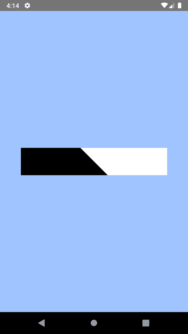
The black and white gradient again, with the fixed code. Hooray! It's actually 45 degrees!